 Introduction
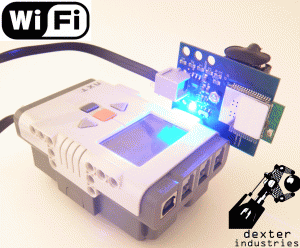
The Dexter Industries Wifi sensor for Lego Mindstorms NXT is a sensor designed to allow your NXT to connect to the internet via a local Wifi network. The sensor operates with standard 802.11 b/g/n access and can be configured to run on the vast majority of home networks.
The Dexter Industries Wifi Sensor connects to the NXT via the high speed communications Port 4. The wifi sensor is powered by an external 9V battery.
The Wifi Sensor comes with a full range of security options and is able to connect with WPA2-PSK, WPA, and WEP security networks.
Hardware

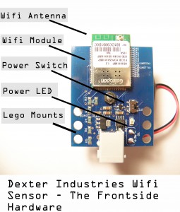
Layout
- Wifi Module: This is where wifi signals are processed and firmware is stored.
- Wifi Antenna: This is where the Wifi sensor sends and receives data. This area should be kept clear of metal obstructions.
- Power Switch: Turn this on and off to turn the sensor on and off.
- Power LED: This LED will light when the power is turned on.
- Lego Mounts: These are provided to integrate into LEGO Hardware.
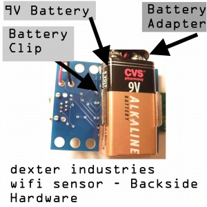
On the backside of the sensor:
- Battery Clip: This is where a 9V battery is connected.
- Battery Adapter: This is where you connect the 9V battery to power the sensor.

Startup
- Battery: Place a fresh 9V battery in the battery clip on the back of the sensor, and attach the battery connector. Push the Power Switch towards the Female NXT Adapter. The bright blue LED should turn on.
- Connection: Connect the sensor to Port 4 of the NXT. The sensor uses the high-speed RS-485 line to connect with the NXT. The sensor can only be connected to Port 4 and will not work on Ports 1-3.
Hints and Warnings
- Baud Rates (Between the NXT and the Wifi Sensor): The default baud rate of the Wifi sensor is 9600 baud, 8 bit characters, with no parity and 1 stop bit. Allowed baud rates include 9600, 19200, 38400, 57600, 115200, 230400, 460800, 921600.
- Prevent stress damage to the board: be sure to use both sets of NXT holes to mount to LEGO contraptions and mount in such a way that the circuit board is not bent or stressed.
- Keep the Antenna Clear: The module should be mounted so that the Wifi antenna (the green circuit board extending past the blue circuit board) is free of metal obstructions.
- The NXT can be mounted to your contraption using the NXT cross-style pegs.
Software
Overview

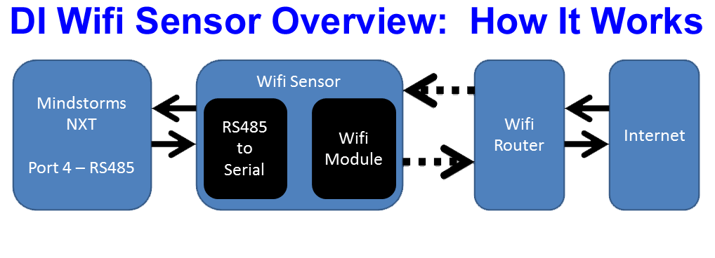
An Overview of how the Wifi Sensor Connects the NXT to the Internet
The above graphic illustrates how the Wifi sensor connects the NXT to the internet. The sensor is connected on Port 4 of the NXT and communicates via RS-485 protocol to the Wifi module on the Wifi Sensor. The Wifi module connects to a wifi router (via radio signals) which in turn connects to the internet.
To connect the NXT to the internet, a few steps must be taken to configure the Wifi Sensor. These are listed below and explained in more detail further down the page.
- Initialize the NXT and module.
- Select authentication method. This is the type of network you’ll be joining, ie a WEP, WPA, WPA2, or Open network.
- Connect to the Wifi router.
- Authenticate security on the wifi router.
- Obtain the IP address.
- Communicate over the internet.
AT Commands
The Wifi module can be programmed and controlled via AT commands from the NXT module. These commands are used to configure everything from serial communication protocol between the NXT and the wifi to the password for your wifi router. AT commands are generally sent via arrays of characters to the module. AT Commands generally take the form
ATstring
where string is the command and parameters you intend to send to the module. A command must be followed by a carriage return symbol and most programming languages require a ’13’ character at the end of the array (see examples below). A complete set of commands can be found in the DI Wifi Commands document.
NXT to Sensor Communication
The NXT communicates with the Wifi sensor via Port 4 RS-485 serial communications. The Wifi module defaults to 9600 baud, using 8 bit characters with no parity bits and one stopbit. Any changes to this configuration that were made in a previous session will be lost when power is lost. To make changes in the communications parameters that will persist across power cycling, the relevant changes must be saved into the power-on profile.
Initialize the NXT and Module
Initializing the NXT is simply activating the High Speed Port 4. This should be done according to the API you are programming your NXT in. See below for more details on the individual programming languages.
Initializing the Wifi Module requires a few more steps.
All Echo Off: First, we will turn all echo off. The Wifi module’s default setting is to echo back all input. To turn this off, send the command “ATE0” (The last character is the number zero). See section 4.2 of the DI Wifi commands.
Setup Flow Control: Next, we will configure the serial flow control. This will enable the software to control the flow of data. We send “AT&K1” to enable software flow control. See section 4.2.2 for more information.
Setup Verbose Response: After many commands you send the module, a response is set back to verify the outcome (mostly an “OK” or “ERROR” to verify success or failure of executing the command you just sent). These can be made “Verbose”, where the module returns a complete word such as “OK”. The response can also be configured to be “Non-verbose”, where the module returns a number representing a value (for example it returns the number “0” instead of “OK” and the number “1” instead of “Error”). To set the response to Verbose, we send the module “ATV1”. For more information, see section 4.1.3 of the DI Wifi Commands.
Setting Authentication Mode
To connect to a Wifi network you will need to set the authentication mode the module will use to connect to a Wifi Network. Authentication is done with the command
AT+WAUTH=n
Where n is 0 for no authentication, 1 for Open authentication, and 2 for WEP. This authentication mode command is specific to WEPencryption; if WPA/WPA2 operation is employed, the authentication mode may be left at the default value “ None”. See section 4.8.1 for more details.
Connecting to WPA Networks
To connect to a WPA network you will need the network SSID and the WPA passphrase. You will first generate have the module calculate a key. Calculation of the key can be time and energy consuming. This key only needs to generated once so we recommend that the key be initially generated and saved to a profile. The command to generate the key is
AT+WPAPSK=<SSID>,<PASSPHRASE>
For more information on generating a WPA key, see section 4.8.4.
Next we will associate to a network. We do this with the command
AT+WA=<SSID>
Where <SSID> is the SSID of the network. See section 4.7.7 for more detailed information.
Connecting to WEP Networks
To connect to a WEP network, you will need the WEP key and name of the Wifi network we will be connecting to.
First, we will set the WEP key. The WEP key is sent with the following command: AT+WWEPn=<key>
Where n is the key index, and key is the 10 to 104 bit WEP key.
Next, we will set the infrastructure mode. For most networks, this will be an infrastructure type mode. To establish a network mode, use the following command: AT+WM=n
If n is 0, the mode is set to infrastructure and if n is 1, the mode is set to ad hoc.
Next we will set the authentication mode. The authentication mode is set using the following command: AT+WAUTH=n
Where if n is 0, the network is WPA; if n is 1, the wifi network is open or WEP, and 2 if it is shared with WEP. For a standard WEP network, n will be 1.
Finally, we will associate with a Wifi network. To associate with a WEP Wifi network, we will call the following command: AT+WA=<SSID>[,[<BSSID>][,<Ch>]]
Where <SSID> is the SSID (or name) of the wifi network and the items in [ ] are optional.
After calling this command, we should be connected to the wifi network.
Obtaining an IP Address
The Wifi Sensor can connect via a dynamically assigned IP Address or manually assign a static IP. The most common method of connection is to dynamically assign and IP. This can be done on the Wifi sensor with Dynamic Host Configuration Protocol (DHCP). Information o static configuration of network parameters can be found in section 4.10.3.
The command to enable or disable DHCP is
AT+NDHCP=n
Where if n is 0, DHCP is disabled and if n is 1, DHCP is enabled.
When DHCP is enabled, after connecting to a network, the wifi sensor will report an IP via the serial line.
Communicating over the Internet
In General:
-
- CID – Each time the sensor connects to the internet, whether its a server or client, HTTP or TCP etc, the Wifi module will report a CID. CID is Connection Indentifier, a number indicating the connection destination or destination source. Each time the NXT sends or receives information, this number will be referenced.
- Data Transfer – Data transfer will need to be surrounded by a sequence that depends on the type of connection being established. The sequence will start with an <ESC> character, followed by an identifier character, followed by the CID.
HTTP Protocol: The Dexter Industries Wifi sensor supports both HTTP client and Server. Examples of both are contained in the Examples package (.zip) in our downloads section and on our Wifi Week special. For HTTP client examples, see our post on interacting with Twitter.
TCP Protocol: The Dexter Industries Wifi sensor supports both TCP client and server. An example of a TCP server is contained in the Examples package (.zip) in our downloads section and on our Wifi Week special.
UDP Protocol: The Dexter Industries Wifi sensor supports both UDP client and UDP server connections. An example of a UDP server is contained in the Examples package (.zip) in our downloads section.
Utilities: Many utilities exist to enhance the Wifi Sensor. Some are listed below with their structure and call. See our Wifi Week Special for some examples.
Check Connection Status – The connection status of the wifi sensor can be checked with this call. When this command is called, the connection status, IP number of the wifi sensor is sent from the sensor to the NXT. There are two commands to check the status of the connection:
AT+WSTATUS - Upon deployment of this command, the Wifi sensor reports the current network configuration of the wifi sensor to the NXT. This command returns the current IP of the sensor.
AT+NSTAT=? - Upon deployment of this command, the Wifi sensor reports the status of the network, including the MAC address, WLAN state, SSID, Mode, transmit and receive counts.
Network Scanning – The command for scanning can be modified extensively to search for a particular network. An example of this is including in our RobotC examples in our download section. It can also be used to scan for available networks:
AT+WS - Returns the available networks in range of the WIFI sensor.
DNS Lookup – This command can be used to find the IP address of a particular URL. For example:
AT+DNSLOOKUP=http://www.dexterindustries.com - This command will return the IP of the Dexter Industries website.
Ping – This command can be used to ping an internet address. An IP address must be used to ping. An example of this is including in our RobotC examples in our download section.
AT+PING=123.321.123.321 - Will return the results of repeated pings until the sequence <Esc> C is sent to the wifi Sensor.
Check Battery Status – Battery checking is a multiple-step process. First the battery check command must be initiated. After this is initiated, the voltage of the battery can be called at any time.
AT+BCHKSTRT=<frequency> - The variable frequency is a number between 1 and 100 representing the frequency of battery checking; how many sent packets of information will be sent between battery checks.
AT+BATTVALGET - Returns the battery value in volts.
Power Save Mode – The Dexter Industries wifi sensor can be put into sleep mode. The sensor can be awoken by simply sending any information to it, however a dummy variable should be sent as the sensor requires a few milliseconds to awake.
AT+PSDSLEEP - This call will reduce the power consumption of the sensor to below 1 mW.
RobotC
Examples for HTTP, TCP, and UDP are developed and ready for download in our downloads section.
NXC
Examples for NXC have been developed by Mark Crosbie. You can see examples and walk-through on how to setup a web server here: http://www.mastincrosbie.com/Marks_LEGO_projects/Webserver_on_the_NXT.html.
Lejos
See our downloads section for LeJOS drivers.
NXT-G
Coming soon.
Other Links and Examples:
- Example: Thingspeak With DIWIFI and LEGO MINDSTORMS NXT
- Example: DI WIFI Week 2: Weather From Google
- Example: The Internet of Things: Pachube With DIWIFI and LEGO MINDSTORMS NXT
- Software: NXC Library
- Hardware: Extending the WIFI Sensor’s Range
- Hardware: Wifi Power! Powering the WIFI sensor with your USB port.
- Example: Lego Street View Car: Part 2
- Project: Twitter Temperature
- Project: Setting Up a Webserver
- Project: Crank Up The Speed!
- Example: PING!
- Example: Communicating with Computers
- Example: Connecting The Wifi Sensor to a Network
- Project: Controlling an NXT from Half Way Around the World


