 Introduction
The Dexter Industries Inertial Motion Unit (IMU) Sensor measures acceleration, tilt, and rotation on all three axes. The sensor combines an accelerometer and a gyroscope into one sensor for the LEGO Mindstorms system. Build robots that know which way is up, can measure tilt, balance themselves, and measure acceleration and rotation on all axes all at once.
Accelerometer: Measure up to 8 g’s on all three axes. Measure between ±2g, ±4g, and ±8g.
Gyroscope: Measures rate of rotation. The sensor can measure ±250, ±500, and ±2,000 degrees per second.
Setup
 Layout
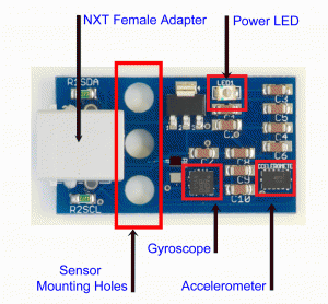
- Accelerometer: measures acceleration on the x, y, and z axes.
- Gyroscope: measures rotation on the x, y, and z axes.
- NXT Female Adapter: connects to the LEGO Mindstorms NXT.
- Power LED: This LED will light when the power is turned on.
- Sensor Mounting Holes: Use these to mount the sensor to your robot.
Axes
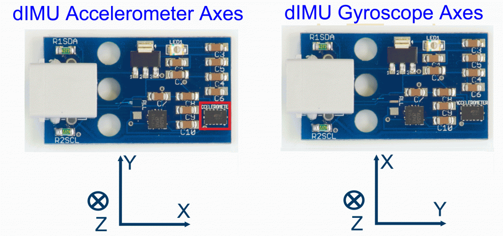
Below are diagrams of the axes of the gyroscope sensor and the accelerometer sensor with directions of the angular axes.
Hints
- Prevent stress damage to the board: be sure to use at least two of NXT holes to mount to LEGO contraptions.
- Calibration: The accelerometer is particularly sensitive and can be calibrated on a flat surface.
- Mounting Holes: LEGO crosses can be used to mount the dIMU to your robot.
Software
NXT-G
NXT-G Blocks are provided for the dIMU. Separate blocks are provided for the gyroscope and for the accelerometer. For instructions on how to install the NXT-G blocks into NXT-G, please see our video. The easiest way to get started with the dIMU is to use the Hello World program found in the NXT-G Block download in our Github Repository.
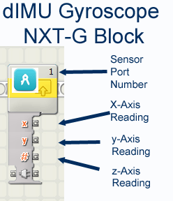 Gyroscope Block – The gyroscope sensor can be read with the Gyroscope Block. The gyroscope block outputs degrees per second (dps) for the axis you select. The below program shows the Gyroscope reading the x-axis. All three axes can be read at once.
Fast Gyroscope Block – The Fast Gyroscope Block is similar to the Gyroscope block. There are two things to be aware of: at the beginning of your program, you must run a normal Gyroscope Block. This will set up the sensor for operation. Use the block to designate the degrees-per-second you would like to read. You must also specify which axis you want the robot to read. The more axes you check, the slower the sensor will read. To get the fastest response, you should only read one axis. Examples are provided in the Fast Gyroscope Block for NXT-G in our downloads section.
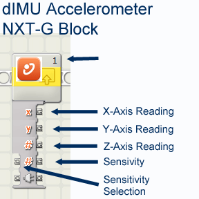 Accelerometer Block – The accelerometer sensor can be read with the Accelerometer Block. The accelerometer block returns milli-G’s (1000th of a G, a unit of gravity) for the axis you select. For example, if the sensor is placed perpendicular to the ground and not moving, it will read “1000” or 1 G. The below program shows the Accelerometer reading the x-axis. All three axes can be read at once.
The Sensitivity Selection input allows you to select the maximum number of G’s to be read by the accelerometer. At times you may want to read very small changes in gravity. For this, the default maximum acceleration reading is 2 G. At other times, you may want to read very large changes in gravity. For this you can input “1” to read a maximum of 4 G or “2” to read a maximum of 8 G.
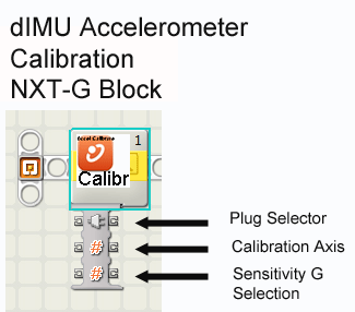 Accelerometer Calibration Block – The accelerometer sensor can be calibrated with the Accelerometer Calibration Block. To calibrate the block, you must select the Gravity Sensitivity (G Select) and the axis of the accelerometer that gravity will be passing through. For example, if you lay the sensor flat on the ground, you must calibrate to the “Z” axis. If you lay the sensor on any other side, you must calibrate to that axis.

An example program of the dIMU using NXT-G to read an accelerometer and gyroscope for the LEGO Mindstorms NXT.
RobotC
RobotC code is provided in the Downloads section of our website. RobotC drivers have been directly incorporated into the latest 3rd Party Drivers Suite, which can be found on the BotBench website.
A basic example for both the gyroscope and the accelerometer are provided in our Downloads section, with detailed commenting to better your understanding of the senor and its operation. The example provides an in-depth explanation of the I2C calls for communicating with the dIMU.
Labview for Lego Mindstorms
VI’s for Labview for Lego Mindstorms are provided by Tufts CEEO. You can find them on our Github Repo.
Lejos
You can find Lejos software in our Github Repo and a great explanation and tutorial on Aswin’s site here.
Calibration of the Accelerometer
Calibration of the Accelerometer is done by writing values to the sensor. The accelerometer stores these values into memory and offsets readings by this value. The calibration will be lost however when power is lost to the sensor.
Technical Specifications
The dIMU is both an accelerometer and a gyroscope. For each part, we’ve outlined the technical specifications below. Both sensors are digital and use unique I2C addresses. This allows them to be used alongside other I2C sensors on the same port.
Accelerometer Technical Specifications
- Axes: Reads acceleration on 3 axes (x, y, and z).
- Multi-sensitivity: Sensitivity can be chosen with the software. The sensor can be set to ±2g, ±4g, and ±8g sensitivity.
- Measures static and dynamic acceleration.
- Minimum Acceleration: 0.015g.
- Maximum Acceleration: ± 8g.
- Features low power consumption, self-test for z-axis, chip-level calibration, and 10-bit value data output.
Gyroscope Technical Specifications
- Axes: Reads rotational speed on 3 axes (x, y, and z).
- Multi-sensitivity: Sensitivity can be chosen with the software. The sensor can be set to ±250, ±500, and ±2,000 degrees per second (dps).
- Minimum Rotational Speed: ±1 dps.
- Maximum Rotational Speed: ±2,000 dps.
- Features low power consumption, 16-bit value data output, sleep mode, and embedded temperature sensor.
Data Sheets
The gyroscope is manufactured by ST and the accelerometer is manufactured by Freescale. Datasheets and application notes for both the accelerometer and gyroscope can be downloaded here.
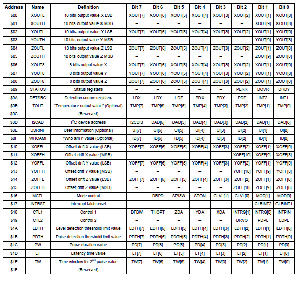
Accelerometer Registers
- Read Address: 0x3A.
- See Page 21 of the Accelerometer datasheet for more details.
- Below is a Register Summary.
Gyroscope Registers
- Read Address: 0xD2.
- See Page 27 of the Gyroscope datasheet for more details.
- Below is a Register Summary.
Helpful Hints
- For both sensors, a sequence of commands must be issued to initialize both the gyroscope and the accelerometer. These commands are illustrated in our RobotC example code.


