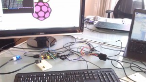
 This is a quick tutorial to show how we hooked up a dIMU (An Accelerometer and Gyroscope for the LEGO MINDSTORMS NXT) to a Raspberry Pi. This is a quick How-To, that assumes you have a Raspberry PI with a Raspbian image on it (If you don’t have Raspbian, you can check out this fantastic tutorial on how to get setup.)
Update: You can find a tutorial on how to use a touch sensor with the Raspberry Pi here.
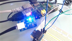
This is also a great example of how to get started with I2C on the Raspberry Pi. We chose the dIMU because it’s easy to access and use, with just four lines to connect (SDA, SCL, GND, and VCC). You may have to make modifications to attach other sensors.
We divide this tutorial up into 4 parts.
First, we get setup on Raspberry Pi to be able to use I2C commands in Python. Then we show how we connect to the Raspberry Pi. Then we show how we connect the Raspberry Pi to the NXT Bread Board Adapter and connect the sensor to the Raspberry Pi. Finally, we show you the Python code for accessing the I2C Sensor.
 1). I2C Stuff
First, get I2C setup on your Raspberry Pi. There’s a great tutorial on how to do it here (http://www.instructables.com/id/Raspberry-Pi-I2C-Python/) . But to boil it down, open up your terminal screen and:
- Run the command “sudo nano /etc/modprobe.d/raspi-blacklist.conf” and add a hash before “blacklist i2c-bcm2708” Save the file.
- Run the command “sudo nano etc/modules” add “i2c-dev” at the end, save the file.
- Run the command “sudo apt-get install i2c-tools” (you will need to be connected to the internet for this to work.
- Run the command “sudo apt-get install python-smbus”
- Run the command “sudo adduser pi i2c” to confugre the last two packages.
And you should now be ready to program I2C in Python.
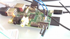 2). Soldering the Adapter.
You’ll need to solder four jumpers or wires to connect the Raspberry Pi to the breadboard. We used jumper wires we found at Sparkfun that are great for prototyping. We also used a female socket to go over the GPIO pins, so we weren’t soldering directly onto the Raspberry Pi.
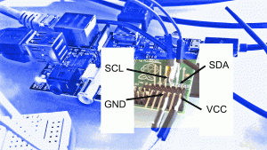 We’ve got a picture of our soldering work to the right. Below we’ll show a better breakout diagram to get to the I2C lines.
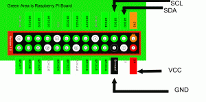
Those four wires are:
- VCC
- GND
- I2C – SCL
- I2C – SDA
Here’s how we’ll be hooking them up to the Raspberry Pi. Below is a diagram of how the four different lines should be attached to the GPIO pins of the Raspberry Pi.
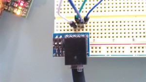
3). Connecting to the Breadboard Adapter
Connecting to the breadboard adapter is very easy at this point. Now that you’ve soldered the jumpers to the GPIO on the Raspberry Pi, the NXT Breadboard Adapter makes this really easy.
Below is a breakout diagram of the NXT Breadboard Adapter as a Sensor. Connect SCL on the Raspberry Pi to SCL on the NXT Adapter, SDA on the Raspberry Pi to SDA on the NXT, GND to GND and VCC to VCC.

 4). Running the Python Program
Finally, the good stuff: getting Python to read data from the sensor. Below is the code for doing reading the LEGO MINDSTORMS sensors over the I2C Line. We used Python 2.7, but this should work in any later version (if it doesn’t please let us know!).
A note about I2C and Python: the majority of the I2C functions use “smbus” in Python. This makes it super-easy. You’re going to use the following commands for most of your low-level transfers:
- bus.write_byte_data
- bus.read_byte_data
The smbus import is really well documented on the web. Doing a quick Google search yields a magnificent amount of information.
The Code: (Download it Here)
[sourcecode language=”python”] # Dexter Industries Example for Connecting the LEGO MINDSTORMS NXT Sensor to the Raspberry Pi# January 2013
# More information at www.dexterindustries.com/howto
#
# License – Attribute; if you use part of this code, please let us know!
# We hope it’s useful to you!
import smbus
import time
bus = smbus.SMBus(0)
# GYROSCOPE CONSTANTS AND VARIABLES ARE DEFINED
address = 105
control_reg_1 = 0x20
control_reg_2 = 0x21
control_reg_3 = 0x22
control_reg_4 = 0x23
control_reg_5 = 0x24
g_x = -1.0000
g_y = -1.0000
g_z = -1.0000
gyro_divisor = 0.0000 # Constant to divide your gyroscope raw return by.
# ACCELEROMETER CONSTANTS AND VARIABLES ARE DEFINED
accel_address = 0x1D
accel_divisor = 0.0000 # Constant to divide accel raw returns by.
a_x = -1.0000
a_y = -1.0000
a_z = -1.0000
def setup_gyro(scale):
global gyro_divisor
bus.write_byte_data(address, control_reg_1, 15)
time.sleep(0.1)
bus.write_byte_data(address, control_reg_2, 0)
time.sleep(0.1)
bus.write_byte_data(address, control_reg_3, 8)
time.sleep(0.1)
if scale == 250:
bus.write_byte_data(address, control_reg_4, 0)
gyro_divisor = 128
time.sleep(0.1)
elif scale == 500:
bus.write_byte_data(address, control_reg_4, 16)
gyro_divisor = 64
time.sleep(0.1)
else:
bus.write_byte_data(address, control_reg_4, 48)
gyro_divisor = 16
time.sleep(0.1)
bus.write_byte_data(address, control_reg_5, 0)
time.sleep(0.1)
def GetGyroValues():
global g_x # Need to be explicitly declared globals at the beginning
global g_y
global g_z
global gyro_divisor
xMSB = bus.read_byte_data(address, 0x29)
xLSB = bus.read_byte_data(address, 0x28)
g_x = ((xMSB << 8) | xLSB) if(g_x > 32767):
g_x = -1*(65536-g_x)
g_x = float(g_x/gyro_divisor)
yMSB = bus.read_byte_data(address, 0x2B)
yLSB = bus.read_byte_data(address, 0x2A)
g_y = ((yMSB << 8) | yLSB) if(g_y > 32767):
g_y = -1*(65536-g_y)
g_y = float(g_y/gyro_divisor)
zMSB = bus.read_byte_data(address, 0x2D)
zLSB = bus.read_byte_data(address, 0x2C)
g_z = ((zMSB << 8) | zLSB) if(g_z > 32767):
g_z = -1*(65536-g_z)
g_z = float(g_z/gyro_divisor)
def setup_accel(range):
# incoming “range” can be 2, 4, or 8. Default is 8 if it’s not 2 or 4.
global accel_divisor
if(range == 2):
bus.write_byte_data(accel_address, 0x16, 0x05)
accel_divisor = 64.0000
elif(range == 4):
bus.write_byte_data(accel_address, 0x16, 0x09)
accel_divisor = 32.0000
else:
bus.write_byte_data(accel_address, 0x16, 0x01)
accel_divisor = 16.0000
def accel_axis_reading(register):
axis_reading = 0.0000
axis_reading = bus.read_word_data(accel_address, register)
if(axis_reading > 511):
axis_reading = -1*(1023-axis_reading) # This deals with 2’s compliment of raw reading 10 bit number
axis_reading = float(axis_reading/accel_divisor)
return axis_reading
def GetAccelValues():
global a_x
global a_y
global a_z
a_x = float(accel_axis_reading(0x00))
a_y = accel_axis_reading(0x02)
a_z = accel_axis_reading(0x04)
def main():
# Initialize the gyroscope and accelerometer
setup_gyro(500)
setup_accel(2)
while True:
# Update the values
GetGyroValues();
GetAccelValues();
# Print the values
print “Gyro Values: %d, %d, %d” % (g_x, g_y, g_z)
print “Accel Values: %0.4f, %0.4f, %0.4f” % (a_x, a_y, a_z)
time.sleep(0.5) # Sleep 1 second
print ” ”
#if __name__==’__main__’:
main()
[/sourcecode]If python is installed properly, you should be able to copy the code into a new file and type
python Raspberry_Pi_LEGO.py
And see the results!
So if you’ve read this far, you are really interested in Raspberry Pi and the LEGO MINDSTORMS. Drop us a line and let us know what you’d like to see next!
Learn More!
If you liked this tutorial, consider purchasing the Breadboard Adapter for LEGO Mindstorms here.


