Introduction
 The line follower is getting an upgrade in 2019! This sensor allows a mobile robot, like the GoPiGo or the BrickPi, to follow a black line on the floor from start to finish.
You can use it to program your robot to deliver cookies from the kitchen to your room, learn the basics of automated warehouses, or self-driving cars!
The line follower, like all our other sensors, does not require any soldering.
Technical Information
- I2C sensor with Grove connector
- Six (6) analog sensors, each giving a value bewteen zero (0) and one (1) depending on how much light it is receiving back from the floor, with 0 indicating black, and 1 indicating white. You can use these values to determine where the line is.
- The sensor can be polled at an impressive 120 Hz.
- An easy library and a driver-level library are available and fully documented. The easy library provides methods that do the heavy lifting for you.
Description of parts
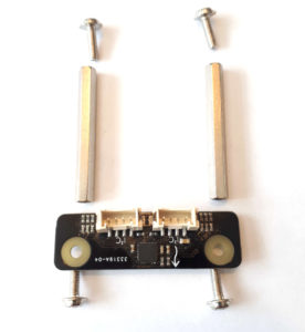
With this updated line follower, you are getting :
- the black sensor
- two (2) long hex spacer posts
- four (4) bolts (screws)
You will need a small Phillips screwdriver, like the one included with the GoPiGo3.
Assembly on the GoPiGo3
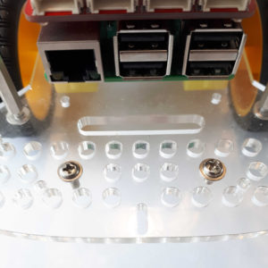
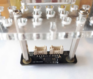
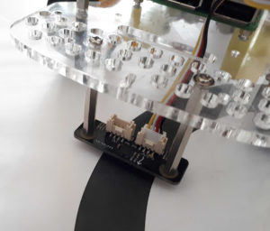
The GoPiGo3 bottom acrylic has two dedicated holes in the front. Insert two of the bolts.
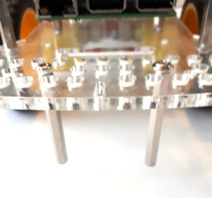
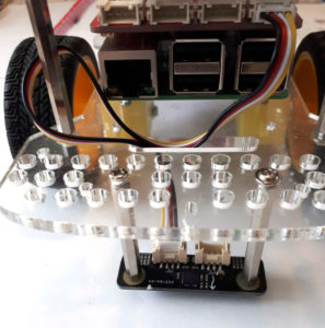
Attach the two posts through the acrylic. Use the screwdriver to tighten them up but not too tight.
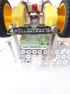
Flip the GoPiGo3 on its back and position the line follower sensor so the sensors are at the back, near the motors and wheels, and the logo is facing the front. Use the remaining bolts to attach the sensor to the posts.
Flip the GoPiGo back to its normal position. Verify that the arrow is indeed pointing forward. Installing the line follower backward would still work but it will be harder to follow a line. If all is well you can tighten all bolts.
Connect the cable. You can use either of the connectors on the line follower sensor. You can connect to either of the I2C connectors on the GoPiGo3. Please note that the line follower can also be connected to one of the AD ports if you’re using Raspbian For Robots (and not DexterOS). It’s a more advanced use, as coding for this setup is slightly different.
Calibration
The line follower requires calibration for best results.
Calibration is always done in two steps:
- Place the line follower sensors over the black line so that all sensors are hovering over the line. Take a reading in this position.
- Place the line follower sensors over the floor away from the black line. It helps if the floor is a very pale color. Take another reading.
The order of those two steps doesn’t matter.
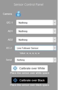
In DexterOS, the calibration is done via the control panel.
As soon as you select the line follower in either one of the I2C options, the buttons will appear.
Place the robot over a white part and press the Calibrate over White button.
Then place the robot over the black line and press the Calibrate over Black button.
To confirm all is well, place the robot over the line as if it was following it. The control panel should display a list of B and w letters that should reflect what the sensors see.
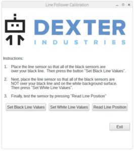
In Raspbian for Robots the calibration is done via the Calibration dialog.
Click the Line Follower Calibration icon to get the dialog up.
Place the line follower over the black line and press the Set Black Line Values button. The dialog will display what the sensor is reading.
Then do the same for the white surface.
You can use Read Line Position to verify it’s properly calibrated.
Assembly on the BrickPi3
Note: while the BrickPi can use the line follower, its acrylic body does not have the proper holes to mount this sensor directly. Because there are so many build options, it would be impossible for us to try to guess where you would need the line follower to be attached. You can attach it according to your build when ready. Calibration is done like above.
Let’s code!
Once assembled, you are ready to start programming!
DexterOS 2.3.0 is the minimum version number required to use the line follower V2.
 Head on over to the Python documentation


