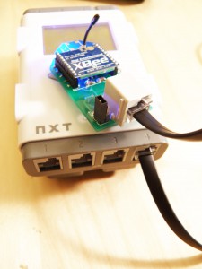
This manual outlines the use of the Dexter Industries NXTBee, NXTBee Naked, and NXTBee PRO. This is the wiki version of the manual. The older (and probably out of date) PDF version can be found here.
Overview and Startup
The Dexter Industries NXTBee sensor brings the Digi XBee radios to your Lego Mindstorms NXT system. These high-speed long-distance radios allow your NXT to communicate with any other device with an XBee radio.
Dexter Industries sells three products:
- The NXTBee – The NXTBee comes ready to go with a Digi 1mW radio installed and programmed. This has range of 100 meters.
- The NXTBee Naked – The NXTBee Naked is just the board. For those that have an XBee radio already. Comes with the parts for upgrading to the NXTBee PRO.
- The NXTBee PRO – The NXTBee PRO comes ready to go with a Digi 60 mW radio. This unit has a range of 1.6 KM and is powered by an external 9V battery.
The NXTBee system is a versatile communication solution for the Mindstorms NXT system. The performance of the NXTBee greatly exceeds Bluetooth, infrared, and other forms of communication currently available to the Lego Mindstorms NXT.
Getting started is easy and requires little configuration. In the case of the NXTBee, you should be able to insert the XBee into Port 4 and begin sending and receiving data. In the case of the NXTBee Pro, you should first attach a 9V battery (see section on configuring the XBee Pro). The NXTBee Naked assumes that you have an XBee radio and can configure the radio in software provided free from Digi (See Chapter 3 for more information).
- Before starting, ensure the Power Supply Jumper on the NXTBee is properly configured. See Figure 1 below.
- The NXTBee and NXTBee PRO use the RS-485 High Speed line on Port 4. The NXTBee will only work in sensor port 4.
- Power Indicator: After connecting the sensor to Port 4, the power LED indicator on the left side of the board should be lit. This is indicating the sensor is receiving power.
- Receive Indicator: When the NXTBee module receives information the blue receive LED will be lit.
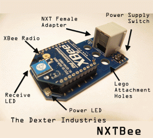
The NXTBee sensor layout is shown to the right in Figure 1.
NXT Female Adapter – The connects the NXT to the NXTBee. This should be connected to Port 4 on the NXT.
Lego Attachement Holes – These holes are used for physically attaching the NXTBee to the NXT.
Power Supply Switch – Use this to configure the power supply for the NXTBee. When connecting the the back two jumpers, the NXTBee draws power from the NXT. When connecting the front two jumpers, the NXTBee draws power from an external source.
XBee Radio – The XBee Radio is the heart of the system. This can be either an XBee or XBee Pro. The radio is mounted on female pin headers and can easily be replaced with another XBee radio.
Receive LED – This LED indicates the XBee is sending information to the NXT.
Power LED – This LED indicates that the NXTBee power is on.
Configuration for Startup
This section explains how to get started with the NXTBee and NXTBee PRO.
NXTBee
- The NXTBee comes fully configured. You should be able to connect the sensor to Port 4 on the NXT and begin using the sensor.
- Power Supply Switch: You should ensure the Power Supply Switch is properly placed. The switch for the NXTBee should be to the back.
NXTBee PRO:
- The NXTBee PRO comes fully configured. However, you will need to attach a 9V battery to properly power the sensor.
- Connecting the 9V: Attach a 9V battery to the 9V battery holder. The power LED should immediately light and will remain lit until the power is turned off. To conserve batteries, remove the 9V battery or disconnect the jumper.
- Power Supply Switch: The power supply switch should be configured all the way to the front of the sensor for the NXTBee PRO.
Configuring an XBee Radio for Use With the NXTBee
This section explains how to configure any XBee radio for use with the NXTBee, NXTBee PRO, or NXTBee Naked. These instructions are for configuring an XBee module not purchased from Dexter Industries for use with the NXBee.
Xbee radios from Dexter Industries come properly configured. If you bought a NXTBee or NXTBee PRO from Dexter Industries, you do not need to complete these steps.
Why?
The XBee firmware must be configured properly to communicate with the NXT. XBee radios do not come from the factory properly configured for RS485 communication. Furthermore, XBee radios often come with outdated firmware, which can limit the functionality of the radio.
Configuring and updating the firmware should not take more than 5 minutes if you have the proper software and hardware.
Tools
To configure an XBee radio, you will need:
- An XBee or XBee-Pro.
- An XBee-to-Serial adapter.
- Digi X-CTU software. (Free from www.digi.com)
Configuring the XBee Radio
Take the following steps to configure the XBee radio for use with the NXT.
- Connect the XBee-to-Serial adapter to your computer. Slide the XBee in place.
- Start the Digi X-CTU software. This can be downloaded for free from Digi.com.
- In X-CTU, verify your XBee or XBee Pro is connected:
- Select the “PC Settings” tab.
- Click “Test / Query”
- Select the “Modem Configuration” tab.
- Check “Always Update Firmware”.
- In the control window, scroll down to “IO Settings”
- Select “(7) D7 – DI07 Configuration” and set to “7-RS485 TX ENABLE HI”.
- Click the “Write” button in “Modem Parameters and Firmware.
- Remove the XBee module from your adapter and slide into the NXTBee naked socket.
Your NXTBee is ready to use.
Configuring the NXTBee as a NXTBee PRO
This section will give some pointers on getting started with the NXTBee PRO.
Any of the NXTBee models can be configured for use with the XBee PRO module. One key difference between the XBee and XBee Pro is that the XBee Pro requires up to 250 mA to operate, far more than the NXT is capable of supplying. To provide the necessary power, you can use a 9V battery to power the module. Instructions on how to modify the NXTBee to operate with an XBee PRO radio are shown below.
Configuring the NXTBee PRO:
Below is an outline for configuring the NXTBee PRO. These directions can be used to either upgrade an NXTBee to a NXTBee PRO or to reconfigure a NXBee Naked into an NXTBee PRO.
Upgrading from NXTBee to NXTBee PRO:
You can upgrade the basic NXTBee to an NXTBee-Pro without purchasing new hardware from Dexter Industries. This process is meant for those that bought a NXTBee or NXTBee Naked and want to upgrade to the NXTBee PRO and have an XBee PRO radio.
Configure the Firmware:
Configure the XBee PRO radio module firmware as described in the previous section. Remove the XBee radio from your NXBee. You must update the firmware and configure the DI07 pin output as described for successful operation with the NXT.
Configuring the Hardware:
To configure the a NXTBee for use with the XBee-Pro you must attach the 9-V adapter and configure the jumpers and attach the 9V battery holder to the bottom of the sensor.
Attach the 9V adapter:
- Solder the red wire to the jumper pin on the outside of the NXTBee PRO.
- Solder the black wire to the jumper pin on the inside of the NXTBee PRO.
Configure the jumpers for external power:
- Move the jumper one pin towards the XBee module.
- The figure to the right shows the power jumper configuration for the NXTBee PRO.
Attach the 9V battery holder:
- Use a 4-40 size screw and bolt to fasten the 9V holder to the bottom of the board. Be careful the screw does not make contact with the electrical components on the board.
- After attaching the 9V battery the blue power LED should light.
NOTE: After configuring the NXTBee for the NXTBee PRO, you can always revert to using the NXTBee. Simply replace the XBee PRO radio with the XBee radio and revert the power jumpers to their original configuration. You do NOT need to remove the 9V battery holder or adapter.
Software
RobotC and NXC
Many examples have been developed for the NXTBee in both RobotC and NXC. They can be found in our downloads section.
NXT-G Block and Labview VI development
Milluzzi Labs and Dexter Industries have created a Google group and code site to test and develop the NXT-G Blocks and Labview VI’s for the NXTBee. The NXTBee is the first sensor to use the high-speed RS-485 communications in Port 4 of the Lego Mindstorms NXT. Because we’re breaking new ground with this sensor and the software to support it, we’re starting a Google group and code site for beta-testers to share experiences, report bugs, and collaborate to improve the software.
- When posting to the group, try to fully describe any errors you experience, as well as the operating conditions under which you experienced the error.
- And of course, be nice. Bad grammar is acceptable but bad manners are not.
Participate: Visit the Google Code Site: http://code.google.com/p/nxtbee-nxt-g/
Other Links and Examples:
- Project: Live Plotting Map Data from the dGPS
- Project: NXTBee Segway
- Project: NXTBee Controlled RC Car
- Tutorial: Setting up a NXTBee Secure Network For Mindstorm NXT
- Example: NXC Examples
- Example: Integrating Lego Mindstorm NXT and Arduino
- Example: NXTBee Lookup Table
- Example: NXTBee Tutorial
- Example: Multi-Robot Communication Using the NXTBee
- Examples: Multirobot Roundup
- Example: Lego Streetview Project
- Tutorial: NXTBee in Labview for LEGO MINDSTORMS
FAQ:
Q: Will “S2” or Series 2 style Xbee radios fit into the NXTBee?
A: Yes, S2 or Series 2 style Xbee radios will work with the NXTBee.
Q:What baud rate does the NXTBee ship with?
A: All NXTBee radios ship pre-programmed with a baud rate of 9600.
Q:Will the NXTBee NXT-G work with standard NXT-G firmware?
A: No. New firmware comes bundled with the NXT-G blocks for the NXTBee. NXT-G blocks will not work without this updated firmware.


